


A METHODOLOGY FOR CONSTRUCTING AN ENCLOSURE
FOR INDIRECT OBSERVATION
STEP 1: Specify the Observing Location. In this example, we will be using a location in southwest Denton, Texas:
Latitude: 33°09’ N ; Longitude: 97° 07’ W
Magnetic Variation ~ 6° E
STEP 2: Specify the Clock Time for the observations.
Standard hour divisions are on multiples of 15° of longitude. The Observing Location is bracketed by the 90°W and 105°W lines of longitude; hence, Local Noon will be:
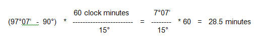
Therefore, readings should be taken at 12:28:30pm
(add 1 hour if Daylight Savings Time is in effect)
STEP 3: Specify Maximum and Minimum Solar Elevations
Consider the plane containing both the true north/south line at the Observer’s location and the Zenith. At Local Noon, the time of the observations:
A METHODOLOGY FOR CONSTRUCTING AN ENCLOSURE
FOR INDIRECT OBSERVATION
STEP 1: Specify the Observing Location. In this example, we will be using a location in southwest Denton, Texas:
Latitude: 33°09’ N ; Longitude: 97° 07’ W
Magnetic Variation ~ 6° E
STEP 2: Specify the Clock Time for the observations.
Standard hour divisions are on multiples of 15° of longitude. The Observing Location is bracketed by the 90°W and 105°W lines of longitude; hence, Local Noon will be:
Therefore, readings should be taken at 12:28:30pm
(add 1 hour if Daylight Savings Time is in effect)
STEP 3: Specify Maximum and Minimum Solar Elevations
Consider the plane containing both the true north/south line at the Observer’s location and the Zenith. At Local Noon, the time of the observations:
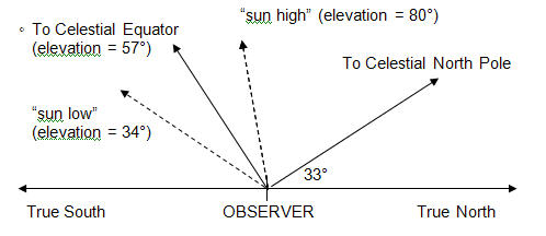
a) Specify the line towards the Celestial North Pole (90° North Declination). Numerically, it is the same elevation as the Observer’s Latitude – here, ~ 33°
b) Specify the line towards the Celestial equator; it is 90° away from the line towards the Celestial North Pole. Numerically, it will have an elevation of 90° minus the Observer’s Latitude, . . .
here, 90° – 33° , or 57°
c) Specify the lines of maximum and minimum solar elevations (these are the Summer and Winter Solstice points). These will be the elevation of the line to the Celestial Equator plus/minus the tilt of the Earth’s axis relative to the orbital plane (~ 23°).
here, 57° + 23°, or 80° to maximum “sun high”
57° – 23°, or 34° to minimum “sun low”
STEP 4: Delineate the boundaries of the analemma. In this example, we’ll be calculating how to place the entire analemma on a single 8½” x 11” piece of paper, and allowing for ~ ½” margin at each solstice.
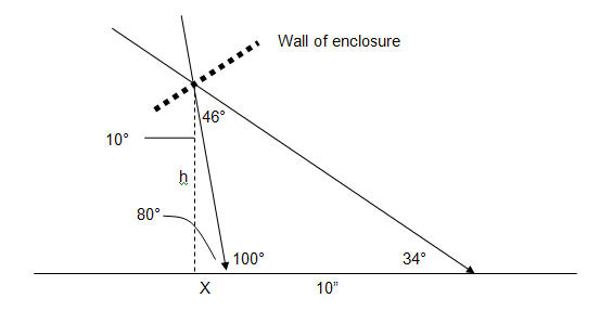
a) Specify the sun-high and sun-low lines; here, they are lines with elevations of 80° and 34°, respectively.
b) Specify the supplementary angle to the sun-high line on the base of the enclosure; here, 180° – 80° = 100°
c) Specify the two angles at the opening of the wall of the enclosure:
i. 46° between the sun-high and sun-low lines (this is twice the tilt of the Earth’s axis relative to
its orbital plane)
ii. 10° between the sun-high line and the vertical
d) Specify the two unknowns:
i. “x” = the distance from the (southern) edge of the analemma to the point directly below the
opening in the wall of the enclosure; it contains the ½” margin on the 8½” x 11” piece of paper
ii. “h” = the height of the opening in the wall of the enclosure above the base of the enclosure
e) The math; the definition of a tangent and a little algebra is all that is required:
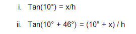
Put x in terms of h and equate:
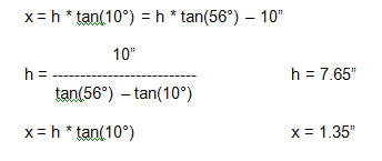
Therefore, poke the hole ~ 7 5/8” above the base of the enclosure;
as “x” contains an allowance of 0.50” from the solstice point to the edge of the paper,
place the south edge of the paper ~ 7/8” north of the hole.
STEP 5: Complete the Enclosure: A double-layered cardboard box with a 14” x 18” base was used is this example. In addition, the following were added:
- A 2” bolt with washers and locking nuts ~ 2” in from each corner were added to provide a level surface.
- The enclosure (and the internal 8½” x 11” piece of paper) was aligned with the long dimension in a true north / south line. The alignment was done using a magnetic compass.
Observers using a magnetic compass for true north / south alignment should be aware that what is
commonly referred to as “Compass Error” comes from two sources:
(1) Variation: the difference in direction to the true north pole and the magnetic north pole; this
difference is available on the Internet, aviation charts, etc.
(2) Deviation: the difference in direction between the magnetic north pole and where the compass
actually points. Deviation arises whenever the magnetic field in the compass’ location is perturbed,
usually due to either presence of iron-containing material or stray magnetic fields due to operation
of electric or electronic equipment.
- The concrete walkway under the enclosure was marked to permit accurate relocation.
- The section of the enclosure wall with the opening was cut and repositioned to be perpendicular to the Celestial Equator. This was to minimize difficulty in getting the “sun-high” beam through the wall.
Additional Links
Printable .pdf version of this page
Return to Introduction Page